| |
USING MY UNI
Using my UNI requires certain considerations. Firstly, it is seldom possible
to overload this
Universal Power Transformer prototype with more than some 10% drawn power.
The only situation
is when all secondary windings are NOT used and(/or) ALL primary windings
are in use. In this case
it's actually possible to overload one or two of S1-S8 with some 100% higher
current than nominal.
Please be aware of the generated heat (which never should exceed 80C) though.
For a more specific
Mains and/or OPT analysis, see The UNI Loss Model and/or Using my UNI as an
OPT respectively.
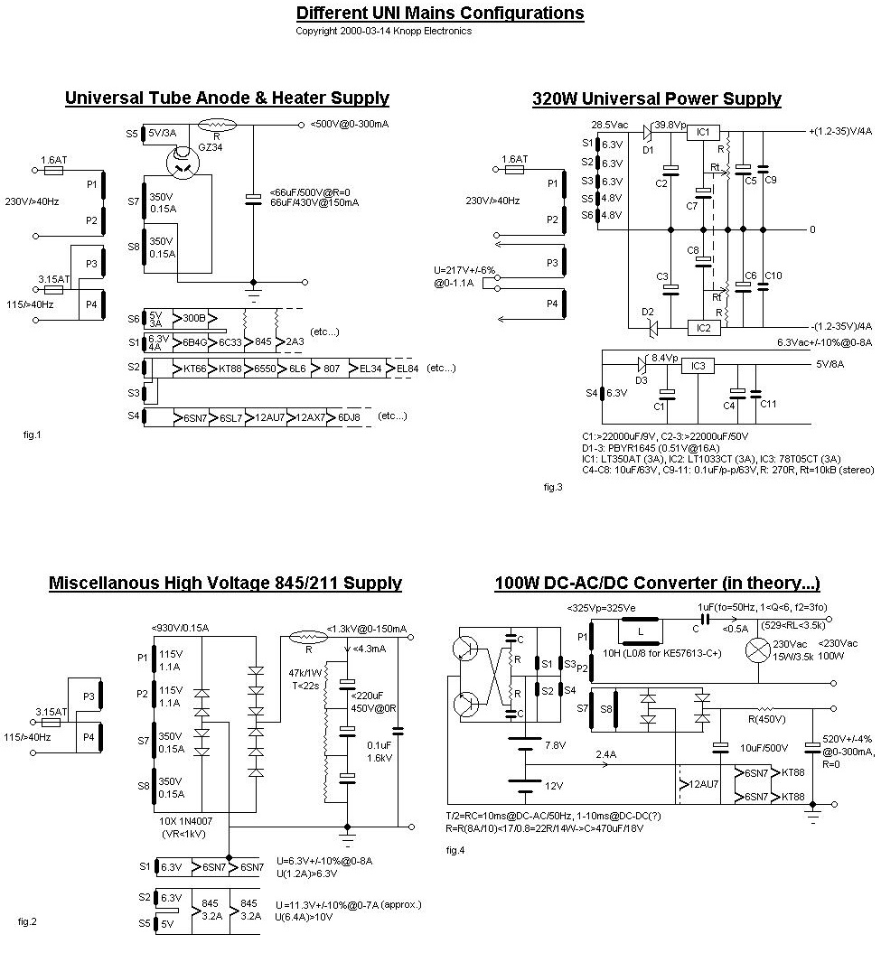
Figure 1 speaks for itself but it should be noted that output voltage may be
tuned from some
500V to 450V with the use of R as noted. It is recommended that C never may
exceed some 66uF while
being driven directly from GZ34 (or whatever). This is due to the fact of
high capacitive
current peaks which may be estimated by calculating w*C*Up (=10.3Ap) vs Up/(Zdrive
+ 2rp + R) and
whichever comes first (4.6Ap@Up/Zdtot in this R=0 case). Even this 4.6Ap
will however probably reduce
the MTBF for the rectifyer tube.
The figure 2 resistive and capacitive values are calculated with the just
mentioned considerations
(220uF/3=73uF). It is furthermore notable that you more or less have to
parallel the capacitors
with leakage/bias-resistors. The reason is different dielectric losses or
ageing which otherwise
may destroy one or two capacitors due to over voltage. I've used the lowest
possible 1W value
(47k/1W) for this purpose. Please note the quite long time-constant of 22
seconds.
The 0.1uF/1.6kV capacitor is used to eliminate HF current peaks which are
more prominent in
solid state rectifyers (due to faster as well as lower internal diode
resistance).
The reason for 2*3 diodes in the FW HV end, is that 1N4007 can't withstand
more than 1kV reverse
polarity whereas the maximum reverse voltage actually is 2.6kV
(1.3kVdc--1.3kVac) here.
Figure 3 shows my version of an Universal High Power Supply. You may of
couse configure the UNI
in some optional other manner (and for instance use the S7-8 windings also)
but this is more than
satisfactory for me. It is notable that you may draw as much as 2*4 Amps
from the series
connected secondary windings (S1-6) while they only can withstand 4 amps.
The reson is simple
because only half-wave rectification is used. The drawback is however the
need for twice as much
capacitance. Except for the 5V/8A output you may however lower the (C2-C3)
capacitance and expect
a lower maximum stabilized output voltage or current (30V/4A with 10mF
should also suffice AND is cheaper!).
Figure 4 displays my sense of "humour". While it actually seams like a
configuration like this
is possible, you should be aware of the difficulties. One major problem is
the 7.8V battery
(which however may be implemented with 6V plus a number of 1.5V rechargeble
batteries in parallel).
Another related fact is the fact of uncontrolled battery voltage drop but
this may be controlled
by some sort of feedback.
Anyway, something like this configuration IS feasible and the fact of low
leakage inductance might
even enable some 500-1kHz DC to DC conversion (with the consequently lower
capacitance values).
Please let me know if anyone of you customers out there make something like
this work.
I'm especially intertested in DC to AC conversion which, by the way, above
uses one of my dedicated
Williamson OPT's as a pure inductance for series resonance elimination of
the third (as well as higher)
order harmonics. You may however (due to L(U)) have to tune the capacitance
a bit for optimum
higher order harmonic rejection.
There is however also the possibility to use the 5V windings instead but
this still
requires an additional obsolete battery of some 3.7V (as well as lower
output power).
I'm grateful for any tip what so ever. Thanks!
|
|